
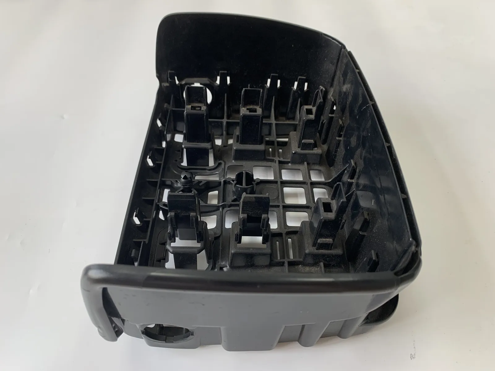
We help buyers release a tool that fills clean on the first trial. Burn marks trace back to one point — the last place to fill, where trapped air has nowhere left to go. DuPont caps its vent land at 0.012–0.020 mm for PA, PBT and PET, so depth follows the resin before the part.
Venting rarely reaches the quotation table. Buyers weigh cavity count, steel grade and cycle time, and the drawing leaves the toolroom carrying a note that says vents per standard practice — a phrase that means whatever the last shop decided it meant.
One camp reads that phrase as harmless. A mould breathes along its parting line, gas that stays behind shows as a small blemish, and nobody rejects a container over a mark the eye barely finds. The other camp has spent weeks re-cutting grooves into hardened steel because a part kept scorching at the end of fill, on a tool that had already passed its first-article run.
The argument is not about whether vents matter. It is about which number sets them. Buyers tend to size the groove by the part, assuming a bigger shot needs a deeper vent, while every published venting specification we compared sizes it by the melt instead, and caps it. The two rules point in opposite directions the moment a job moves from PP to PBT, or from virgin resin to a recycled blend that carries extra volatiles.
Four questions frame what follows:
- Why does a part scorch at the last point to fill, and not somewhere earlier?
- How deep should the vent land run for the resins we mould most — PE, PP, ABS, PC and PA?
- Where do five published venting specifications agree, and where do they contradict each other?
- What changes when the resin carries recycled content, and what should a buyer confirm before sign-off?
Short answer, assembled from five published specifications and from the toolroom facts we publish ourselves. The vent land stays shallow: DuPont’s guides hold PA, PBT, PET and HTN grades at 0.012–0.020 mm, POM at 0.030 mm and TPC-ET at 0.040 mm, while a general design reference puts the working band at 0.02–0.05 mm and splits its maximum by melt viscosity — 0.01–0.03 mm for thin melts, 0.03–0.05 mm for medium, 0.05–0.08 mm for stiff ones. Land length is the second number, kept at 0.8–1.0 mm, after which the groove deepens past 0.8 mm and opens further once it sits 25 mm clear of the cavity. Depth guards against flash. Count and placement guard against burning. A tool that gets depth right and count wrong still scorches parts.
Key takeaways
- Depth ceiling: DuPont holds PA, PBT, PET and HTN grades at 0.012–0.020 mm, POM at 0.030 mm and TPC-ET at 0.040 mm, so the melt sets the limit before shot weight does.
- Viscosity splits the band: the general reference caps vent depth at 0.01–0.03 mm for thin melts, 0.03–0.05 mm for medium and 0.05–0.08 mm for stiff ones.
- Land length is the second number: 0.8–1.0 mm of shallow land, then a groove deeper than 0.8 mm that widens roughly 25 mm from the cavity edge.
- Count beats depth: each gas trap and each weld line needs its own vent, so a part with two bosses and four ribs can carry more vents than a plain housing twice its size.
- Recycled content raises demand: PCR blends bring more volatiles and more deposit, and press-maker guidance calls for adjusted venting and gate placement on recycled and bio-based resins.
- Maintenance is the quiet failure: vents block over a campaign, so a groove that ran clean at trial can be sealed by month three.
Methodology
This article compares published venting specifications instead of our own measurements, and that distinction should shape how you read every figure below. Five documents set the numbers: the DuPont moulding guides for Crastin PBT and Delrin acetal, the Hytrel DYM processing guide, the Zytel HTN processing guide that carries the same depth table, and one general mould design reference covering venting principles. Each stated depth, land length, relief depth and vent width was read directly from the document, tabulated, and compared. Where the sources disagree, both values are shown with their source named.
Anything we state about our own floor comes from the capability and service pages on this site, which we re-read live on 2026-10-12. Capacity figures are drawn from those same published lists rather than from separate reporting.
The comparison has a structural weakness we should name now. Four of the five specifications trace back to a single resin supplier, whose guides cover the supplier’s own resin families and nothing else. The fifth is a general reference that bands depth by melt viscosity class rather than by resin name. Neither type tells a buyer what to cut for a resin outside its scope, and the mapping we offer for PE, PP, ABS and PC follows the viscosity route with that caveat attached.
Why does a part scorch at the last point to fill?
Because that is where the gas ends up. A cavity is never empty of air when the screw pushes forward, and injection adds more gas on top of it. The general reference lists five contributors: air trapped in the cavity and runner, moisture flashing out of the granules, gas released as the polymer decomposes, volatiles driven off additives, and fumes from mould release sprays.
All of that has to leave through the vents as the melt front advances. At the end of fill the fronts converge, the last pocket of gas has the least escape route, and the incoming melt compresses it. Compression raises temperature fast, and a compressed pocket of plastic vapour ignites the resin against the steel. The mark left behind is a scorch, and the mechanism is why it appears at the far corner of a part rather than next to the gate.
Blocked gas does more than discolour. The same reference ties poor venting to short shots, weak weld lines, blisters, dimpled surfaces and eroded cavity steel. The DuPont guides add one warning worth repeating for buyers: with acetal the defect is not always visible. A badly vented POM tool can produce parts with no obvious flaw or an inconspicuous white streak, so a first-article pass on appearance alone proves very little.
But venting is not the only cause of a burnt part. Barrel temperature, residence time and shear all degrade resin before it reaches the cavity, and those defects scatter across the part instead of concentrating at the last point to fill. Location is the clue that separates the two.
How deep should the vent land run for PE, PP, ABS, PC and PA?
Shallow, and shallow for a reason. The vent land sits at the cavity edge, so it has to pass gas while refusing melt. Set it deeper than the resin can tolerate and the cavity no longer seals. The table below pairs the resin families a buyer is most likely to name with the depth the sources allow and the basis for that number.
| Resin or grade | Vent land depth | Basis for the figure |
|---|---|---|
| PA 6 / PA 66 unfilled (Zytel, Minlon, Zytel HTN) | 0.012–0.020 mm | DuPont moulding guide, stated per resin family |
| PBT (Crastin), PET (Rynite), PTT (Sorona) | 0.012–0.020 mm | DuPont moulding guide, stated per resin family |
| POM acetal (Delrin) | Up to 0.030 mm | DuPont moulding guide, POM row of the same table |
| TPC-ET (Hytrel) | 0.040 mm | DuPont processing guide, single value for the family |
| PP and PE | 0.01–0.03 mm | General design reference, thin-melt viscosity band — not a resin-specific figure |
| ABS | 0.03–0.05 mm | General design reference, medium-melt viscosity band — not a resin-specific figure |
| PC | 0.03–0.05 mm | General design reference, medium-melt viscosity band — not a resin-specific figure |
| Filled grades (PA-GF, PP-GF) | 0.05–0.08 mm outer limit | General design reference, stiff-melt band; filler load raises melt viscosity |
Read the row, not the shot weight. A 200 g PP cover and a 12 g PBT connector land in different rows.
From a thin-walled PP lid to a glass-filled PA bracket, the groove deepens as the melt stiffens.
The last four rows carry the caveat. DuPont publishes nothing for PP, PE, ABS or PC in the guides compared here, so those depths come from viscosity bands rather than from resin names, and a grade outside the band moves the number. Depth alone also decides nothing. A deep groove with a long land still traps gas, which is what the next section measures.
Where do the five published specifications agree, and where do they conflict?
Agreement is strongest on depth and on land length. Every specification that names a land length keeps it short — 0.8 to 1.0 mm, with one guide stating the limit as no more than 1 mm. Depth converges into a narrow window: nothing in the set allows more than 0.05 mm, and everything intended to prevent flash sits well below it.
| Specification | Depth allowed | Land length | Relief channel | Vent width |
|---|---|---|---|---|
| Zytel HTN processing guide | 0.012–0.020 mm for PA, PBT, PET and HTN; POM 0.030 mm; TPC-ET 0.040 mm | 0.8–1.0 mm maximum | Deeper than 0.8 mm, opening toward 3 mm | Typically wider than 3 mm |
| Crastin PBT moulding guide | Same depth table as the guide above | 0.8–1.0 mm maximum | Deeper than 0.8 mm, opened to about 3 mm once past 25 mm from the cavity | As wide as feasible, typically wider than 3 mm |
| Delrin acetal guide | POM up to 0.030 mm | No more than 1 mm | Deeper than 0.8 mm, increasing with distance from the cavity | Typically wider than 3 mm |
| Hytrel DYM processing guide | 0.040 mm, stated as a single value | 1.0 mm | Underground channels 6.0 mm wide and 0.5 mm deep | Vent points spaced about 40 mm around the cavity |
| General design reference | 0.02–0.05 mm overall; by viscosity 0.01–0.03, 0.03–0.05 and 0.05–0.08 mm | Not stated in the document | Not stated in the document | 1.5–6 mm |
Two real conflicts fall out of the comparison. The first is coverage: the general reference gives no land length and no relief depth, so a shop working from it alone can size the shallow land and still leave the gas nowhere to go. The second is scale. The general reference stops its thin-melt band at 0.03 mm, yet DuPont allows POM to 0.030 mm and TPC-ET to 0.040 mm — so an identical depth across resin families is not a defensible position.
Keep depth tight. Keep land short. Open the exit. Those three rules hold across every specification in the set.
What changes when the resin carries recycled content, and what should a buyer confirm?
Regulation is pushing recycled content into packaging regardless of how the tool was cut. The EU packaging and packaging waste regulation framework described by extrusion machinery maker Bekum in September 2026 pushes both design-for-recycling and recycled content share, and it is blunt about the consequence: post-consumer recycled material differs from virgin resin in viscosity, melt flow index, colour and contamination, which raises the demand on plasticising, melt flow and process control.
Venting is one of the places that demand lands. Press-maker guidance on recycled and bio-based resins states that moulds and processes often need adjusted venting and gate placement to run them cleanly, and an industry review of circular materials makes the same point about outgassing. The relevant moulding exhibit at PTXPO 2026 pointed the same direction, pairing vacuum venting with fill simulation to clear air traps.
| What the recycled blend changes | What it does to the vent | Where the claim comes from |
|---|---|---|
| Volatiles and outgassing per shot | More gas must leave through the same groove, so total vent area matters more than extra depth | Trade review of circular materials; press-maker guidance |
| Deposit and plate-out on steel | Vents seal over faster, so a groove that ran clean on virgin resin needs attention sooner | Materials guide warning on deposit build-up |
| Melt flow index swing between lots | A thin lot can flash through a groove sized for a stiffer melt, so the thinnest lot sets the safe depth | Machinery maker statement on PCR variation |
| Gate and vent placement | Both may need re-placing when a job switches from virgin to recycled feed | Press-maker guidance on recycled resins |
Set the depth for the thinnest lot in the blend, not the average one. Nothing else in the table changes the rule.
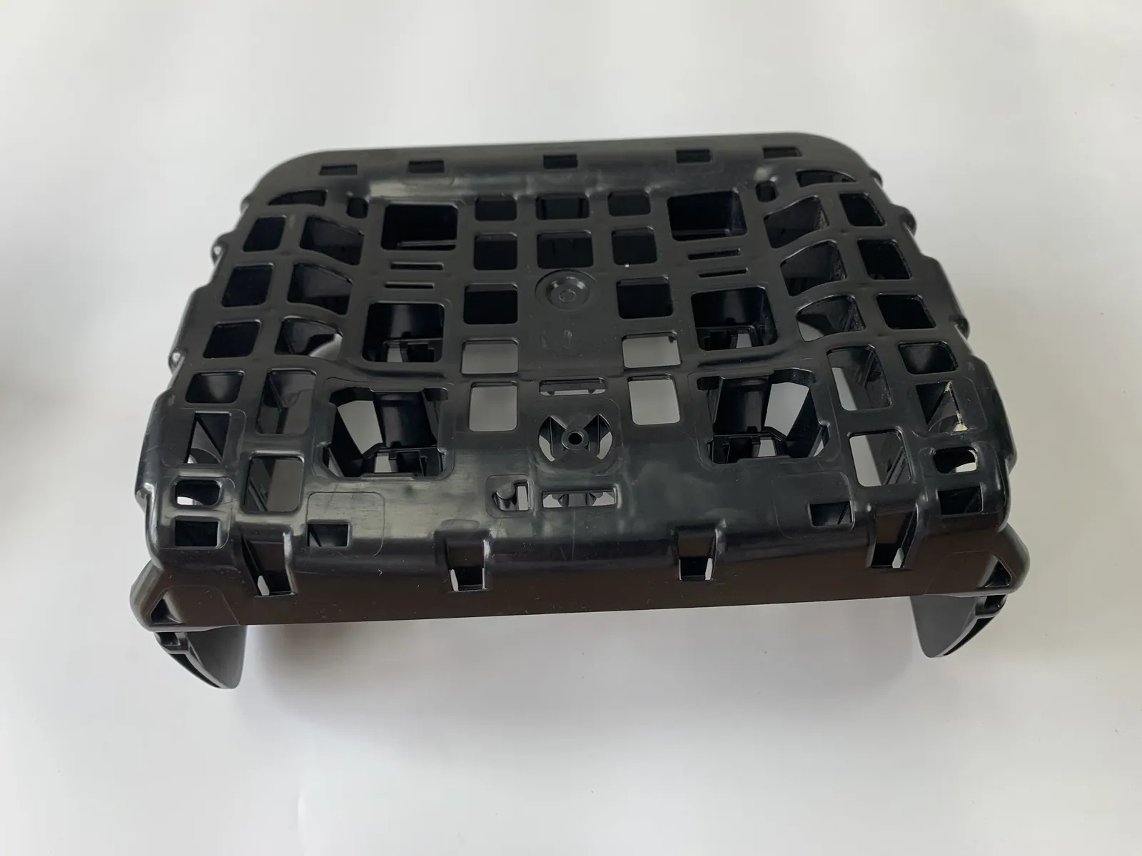
Five checks protect a buyer here, and all five can be written into the RFQ:
- Ask which resin family the vent depth was set for, and have the figure appear on the drawing instead of in a note.
- Ask for the land length and the relief depth behind it, because a deep groove with no exit still holds gas.
- Ask how many gas traps the fill study found, then compare that count with the vents in the design.
- For a recycled blend, ask whether the vents were reviewed after the resin change rather than before it.
- Ask for the vent cleaning interval in the maintenance plan, in shots or in weeks.
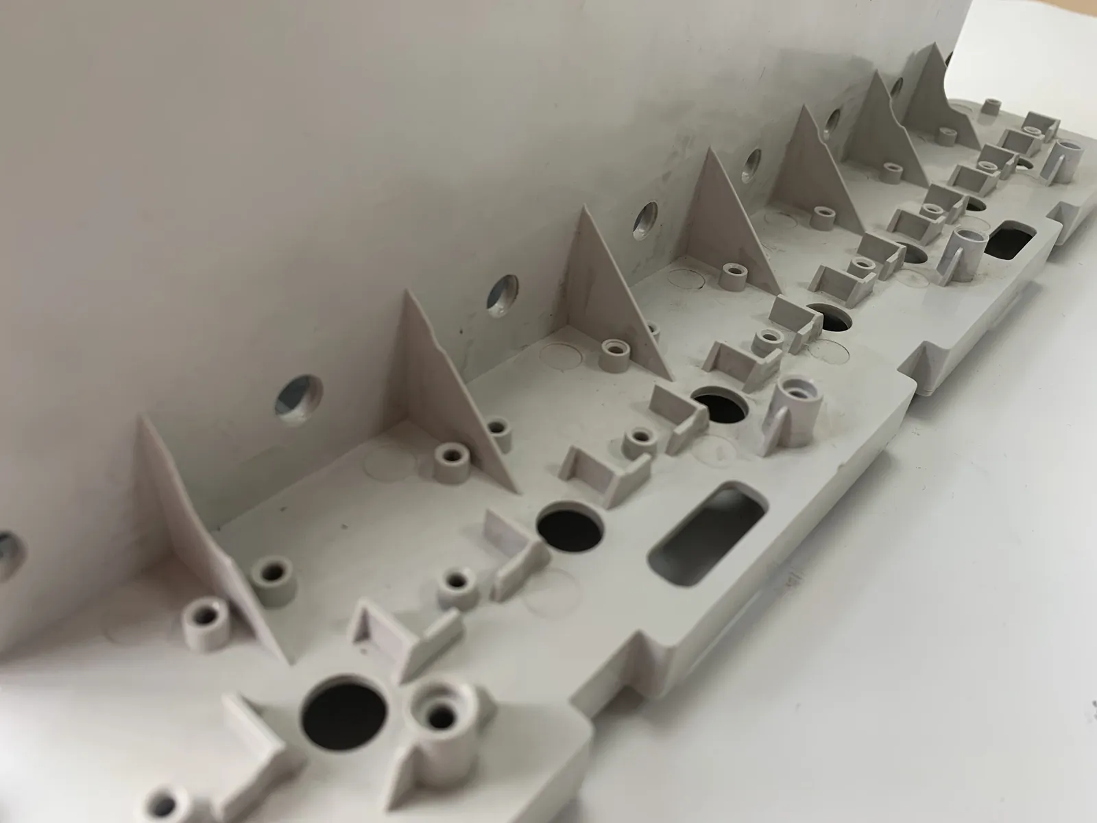
Two conditions decide whether a groove that shallow can be cut at all. In our toolroom the plate faces are ground flat and parallel, and the finer detail goes in afterwards by spark erosion with copper electrodes. A parting face that is not flat turns a 0.02 mm land into a flash path, so a multi-cavity plate is assembled and checked here before any trial shot runs. Moulding here records processing parameters batch by batch, which means a vent change can be read against the run that came before it rather than against memory.
Limitations
The depths quoted here describe a still, clean, correctly built tool, and a working mould is none of the three. Gas volume moves with mould temperature, vents narrow as deposit builds, and a groove measured on a bench is not the groove the melt meets after ten thousand shots. Treat every figure as a starting specification to be confirmed at trial.
The numeric specifications in this article belong to their publishers, not to us. The depth table is DuPont’s, the viscosity bands come from a general mould design reference, and the recycled-resin behaviour is documented by a press maker and by trade media. We publish no vent-depth measurements and no figure for how many scorched parts a correctly vented tool removes, and nothing here should be read as either.
What this means for your RFQ
Vent depth is a property of the resin, not of the part: hold the land where the melt cannot flash, then add vents until every gas trap owns one. Scorch marks are usually a count and placement problem wearing a depth problem’s clothes, which is why deepening a groove so often changes nothing on the part.
That rule has a ceiling. A vent is a maintenance item, and a campaign that never cleans one will burn parts on a tool that was designed correctly — a point that applies with more force once the feed carries recycled content.
We help buyers take a part from drawing to steady production: tool design, machining, trials and first-article measurement handled as one job rather than four handovers. A quotation comes back within 24 hours of your 2D and 3D files reaching info@hongqiangmould.com. Send the resin grade with the drawing, because the vent depth starts there. Flat | Vented | Measured
Frequently asked questions
How deep should a mould vent be for polypropylene? Polypropylene sits in the thin-melt group, where the general design reference caps vent depth at 0.01 to 0.03 mm. DuPont does not publish a resin-specific figure for PP in the guides compared here. Start shallow, confirm at trial, and treat the depth as the point where gas passes but melt does not.
What vent depth does DuPont recommend for nylon and PBT? The DuPont moulding guides compared here allow 0.012 to 0.020 mm for Zytel and Minlon PA resins, Crastin PBT, Rynite PET, Sorona PTT and Zytel HTN grades. Delrin acetal is allowed up to 0.030 mm and Hytrel TPC-ET a fixed 0.040 mm. Depth rises with melt stiffness.
Does a deeper vent groove stop burn marks? Not on its own. Depth is capped by the flash threshold of the resin, so going deeper risks flash before it improves venting. Burn marks usually mean the vent is in the wrong place or there are too few of them. Add vents at the gas traps that the fill study identified.
Why do recycled resins need different venting? Recycled and bio-based feeds carry more volatiles and more deposit than virgin resin, so there is more gas to clear and vents seal sooner. Press-maker guidance calls for adjusted venting and gate placement when a job switches to recycled content. Builders of circular material lines ask for more venting, not less.
How often should mould vents be cleaned? Vent channels block up over a long campaign, so a general design reference advises regular cleaning to keep them open. Deposit builds faster on recycled and filled resins. Put cleaning on a fixed interval rather than waiting for the first scorched part.
Jack works on the tooling and molding team at Hongqiang Mould, an injection mould manufacturer and plastic injection molding supplier. The shop runs 11 presses from 80 to 450 T, 5 CNC machining centres and a metrology room with bridge CMM inspection.